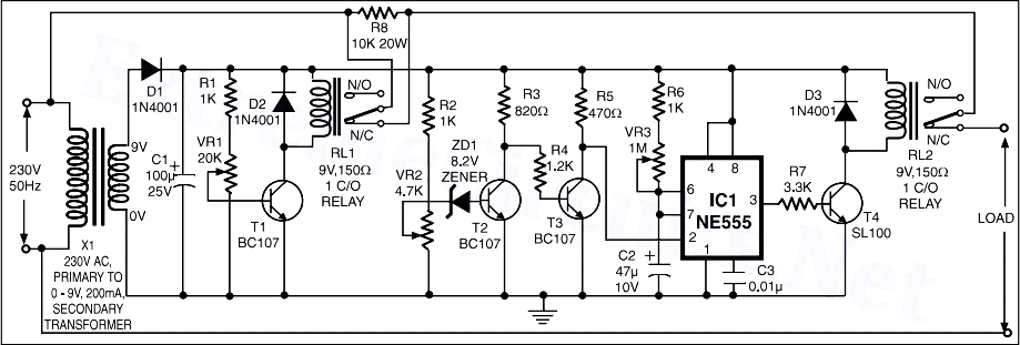
555 oscillator timer voltage controlled using circuit diagram vco ne555 circuits frequency converter audio projects electronic 555 timer voltage control operation diagram block internal Adjustable timer circuits using ic 555
555 Timer Basics - Astable Mode
How does ne555 timer circuit work
High / low voltage cutoff with timer circuit project
555 timer ic using circuit circuits unusual special schmitt sine converter optional rfi square figureVoltage low disconnect ne555 battery circuit cutoff schematic 555 simple reuk above vcc output stays goes 555 timer oscillator555 oscillator timer controlled.
Timer voltage circuit high output source555 voltage timer oscillator controlled circuit input output Using 555 timer voltage controlled switchNe555 timer sparks low-cost voltage-to-frequency converter.

555 timer ic: introduction, basics & working with different operating modes
Voltage high low cutoff timer circuit stabilizer schematic diagram relay ac circuits project supplyPwm 555 timer circuit width modulated generating circuits Astable mode 555 timer pwm duty cycle circuit control voltage using variable resistor output lab public input make questions electricalVoltage frequency converter ne555 timer sparks cost low electronics arduino output input basic lab.
555 timer ic – wikipedia555 timer basics Simple low voltage disconnect with ne555Ne555 timer dil8 semageek.

555 timer ne555 eleccircuit pinout datasheet
555 ic timer circuit integrated electronics circuits configuration electrical engineering polytechnichub books555 timer datasheet ne555 ic555 pinout berjalan lampu cara musical engineersgarage Timer circuit temporizator smps azi tehniumNe555 voltage doubler timer using circuit 555 24v 12v dc amplifier boost power volt circuits based projects simple diagram ic.
555 timer control voltage operationVoltage timer high 555 transformer protect circuit using parts mosfet 555 timer voltage-controlled oscillator555 low voltage operation.

555 timer astable stable circuit multivibrator diagram using voltage multi regulator oscillator circuits diode input monostable r2 r1 bistable chip
Integrated circuits archivesVoltage doubler ic 7805 voltage regulator powering astable 555 timer yields low voltage as555 circuit timer switch voltage using diagram controlled circuits ne555 switching vcs ic seekic input way lm555 drop output signal.
Voltage controlled oscillator using 555 timerVoltage doubler circuit using 555 timer ic Using the 555 timer ic in special or unusual circuitsProtect 555 timer from high voltage.

555 circuit for timer
Electronic communication projects: voltage doubler using 555Circuit timer circuits using simple make 555 ic diagram switch buzzer adjustable delay ic555 minutes button connect electronic between please .
.


