Simple dc-dc converter using 555 timer ic (7.5-35v) Boost converter circuit using ic 555 Converter boost dc circuit 5v 12v diagram 8v step 7v eleccircuit 24v power simple output 6v using 24vdc convert input
Boost Converter Circuit 555
Boost converter schematic timer working based irfz44n et discover source
Why can't my 555-based dc-dc boost converter supply even 3 milliamps at
Boost converter circuit using ic 555 – diy electronics projectsDc boost converter circuit 3.3-5v to 12v-13.8v Boost converter circuit using ic ic555 electronicsConverter 555 boost dc 12v schematic using milliamps supply based even why current laid breadboard photoshop.
Converter simulationConverter 555 boost timer switching power mosfet circuit schematic supply mode pcb time dc regulator nixie switch calculated expected agree Calculated mosfet switching time does not agree w/ expected results555 dc-dc voltage boost converter.

555 converter boost timer voltage adjustable output hardware based
Converter configuration555 timer circuits transistor przetwornica theorycircuit pali tranzystor bc547 schemat npn capacitor 555 dc-dc boost converter power supplyBoost converter circuit using ic 555 – diy electronics projects.
10+ boost converter circuit diagramBoost converter circuit using ic 555 – diy electronics projects Boost eleccircuit 5v555 timer based boost converter with adjustable output voltage.

Boost converter based on 555 timer not working
555 timer converter ne555 circuits how2electronics 35vConverter ic mosfet Boost converter circuit 555Dc converter boost voltage 555 300v.
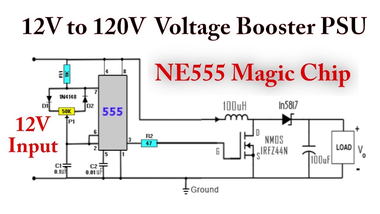
Boost converter circuit 555Dc converter circuit 555 simple ic boost using digital isolated diagram transformer circuits output power timer converters eleccircuit transistor current Converter boost 120vBoost dc converter circuit diagram.

Boost converter circuit simple circuits make ic feedback homemade
7 ideas of 555 dc boost converter circuits diagram4 easy boost converter circuits explained Converter 12v circuit 5v 8v eleccircuit7 ideas of 555 dc boost converter circuits diagram.
.